[Logix] Bài 16: Cấu hình Redundancy với Controllogix qua Ethernet/IP
Hệ thống dự phòng sự cố
Trong các ứng dụng đòi hỏi độ tin cậy cao, người ta thường sử dụng các hệ thống điều khiển có cấu hình Hot Backup, Warm Backup hoặc Redundancy. Về cơ bản hệ thống gồm 2 CPU cùng chạy một chương trình, trong đó một CPU chạy chính, CPU còn lại ở chế độ Standby. Khi CPU chính bị sự cố, CPU Standby sẽ nhận quyền điều khiển để duy trì chương trình hoạt động và trở thành CPU chính. Trong các cấu hình dự phòng sự cố này, Hot backup, warm backup được thực hiện thông qua việc lập trình trong chương trình và thời gian chuyển đổi khi gặp sự cố khoảng vài trăm ms, còn Redundancy thực hiện hoàn toàn dựa trên phần cứng, thời gian chuyển đổi sự cố nhỏ hơn 20ms.
Bài này sẽ giới thiệu cách cấu hình Redundancy với Controllogix thông qua mạng Ethernet/IP.
Cơ bản
- Chỉ Controllogix mới thực hiện được Redundancy (Compactlogix chỉ có thể thực hiện Hot backup, warm backup…)
- Để Redundancy với Ethernet/IP, Firmware thấp nhất là 19.5 (Firmware hỗ trợ Redundancy thường có dạng xx.5yy)
- Trên Chassis CPU chỉ có CPU, Module truyền thông và Module Redundancy (1756-RM), không được gắn Module IO.
- Toàn bộ IO trong hệ thống Redundancy đều là Remote IO
Mô hình hệ thống:

Cấu hình phần cứng
- Chassis A và B hoàn toàn giống nhau:
- Slot 0: CPU L63
- Slot 1: Ethernet module 1756-EN2TR (Dual-Ethernet port), IP: 192.168.1.50
- Slot 7: Ethernet module 1756-EN2TR (Dual-Ethernet port), IP: 192.168.1.60
- Slot 9: Redundancy Module 1756-RM
- Chassis Remote IO:
- Slot 0: Ethernet module 1756-EN2TR, IP: 192.168.1.52
- Slot 5: 1756-IB32
- Slot 6: 1756-OB32
- Network: Remote IO và các mô đun Ethernet kết nối thành mạng vòng DLR (Device Level Ring).
Các bước thực hiện
- Lắp đặt phần cứng trên Chassis A và B giống nhau
- Nâng cấp Firmware cho các Module trên Chassis A và B giống nhau
- Cài đặt địa chỉ IP cho các mô đun tương ứng giữa 2 Chassis giống nhau
- Viết chương trình bình thường, cấu hình Redundancy. Download cho một CPU (Primary), CPU còn lại sẽ tự động cập nhật chương trình qua Module 1756-RM
- Kết nối cáp quang giữa 2 mô đun 1756-RM trên 2 chassis
- Bật nguồn một CPU và download chương trình
- Bật nguồn CPU còn lại
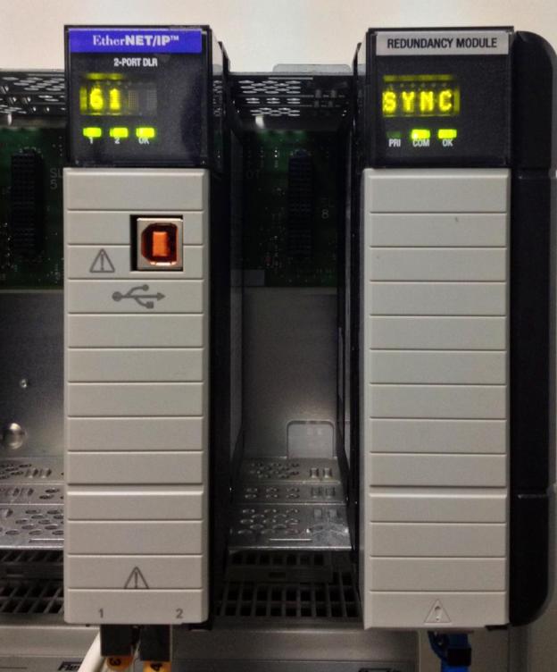
- Kiểm tra trạng thái Redundancy (Module 1756-RM của Chassis Primary hiện “PRIM”, Chassis Standby hiện “SYN”)
Switch Over
Switch Over là việc chuyển từ CPU Primary sang CPU Standby khi CPU Primary bị sự cố. Các trường hợp Switch Over:
- Mất nguồn CPU Primary
- Major Fault trên CPU Primary
- Mất truyền thông trên Chassis Primary
- Người dùng ra lệnh chuyển
Thực hiện
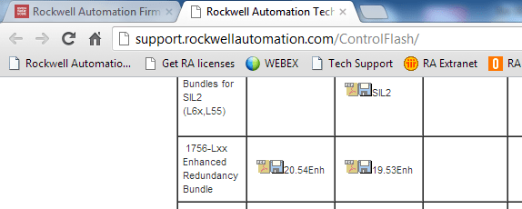
Download Firmware mới 20.54 từ trang Rockwell, cài đặt Firmware và RMC Tool.
Trong Rslogix 5000, khi tạo Project mới chọn Redundancy Enabled:

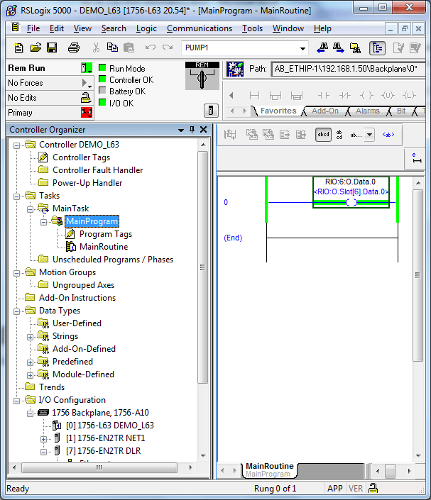
Các bước cấu hình còn lại như chương trình bình thường. Ví dụ luôn ON ngõ ra O6.0:

Download chương trình xuống CPU A:
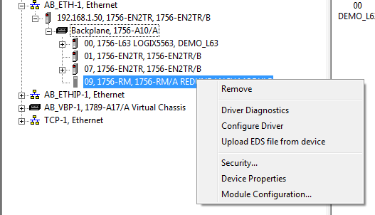
Kiểm tra trên Rslinx Classic, chọn Module Configuration:
Chọn “Sychronization Status” để xem trạng thái. Nếu OK sẽ thấy “Full”:

Module RM trên Chassi Primary khi chạy:

Module RM trên Chassis Standby khi chạy:
Ghi chú
Đây là các bước cơ bản để tạo chương trình Redundancy với Controllogix qua Ethernet/IP. Để sử dụng hiệu quả, cần tìm hiểu thêm các kỹ thuật tối ưu hệ thống. Tài liệu tham khảo: 1756-um535_-en-p.pdf
Tác giả: Giap Van Vy – 2012
[Logix] Lesson 16: Configuring Redundancy with Controllogix via Ethernet/IP
Fault Tolerance System
In high-reliability applications, control systems often use Hot Backup, Warm Backup, or Redundancy configurations. Basically, the system consists of two CPUs running the same program, with one as the main CPU and the other in Standby mode. If the main CPU fails, the Standby CPU takes over to maintain operation and becomes the main CPU. In these configurations, Hot backup and warm backup are implemented via programming, with switchover times of several hundred ms, while Redundancy is fully hardware-based, with switchover times under 20ms.
This lesson introduces how to configure Redundancy with Controllogix via Ethernet/IP.
Basics
- Only Controllogix supports Redundancy (Compactlogix only supports Hot backup, warm backup…)
- For Redundancy with Ethernet/IP, minimum firmware is 19.5 (Redundancy firmware usually has format xx.5yy)
- On the CPU Chassis, only CPU, communication module, and Redundancy module (1756-RM) are allowed; no IO modules.
- All IO in Redundancy systems are Remote IO
System diagram:
Hardware configuration
- Chassis A and B are identical:
- Slot 0: CPU L63
- Slot 1: Ethernet module 1756-EN2TR (Dual-Ethernet port), IP: 192.168.1.50
- Slot 7: Ethernet module 1756-EN2TR (Dual-Ethernet port), IP: 192.168.1.60
- Slot 9: Redundancy Module 1756-RM
- Remote IO Chassis:
- Slot 0: Ethernet module 1756-EN2TR, IP: 192.168.1.52
- Slot 5: 1756-IB32
- Slot 6: 1756-OB32
- Network: Remote IO and Ethernet modules connect in a DLR (Device Level Ring) topology.
Steps
- Install hardware on Chassis A and B identically
- Upgrade firmware for modules on both Chassis
- Set IP addresses for corresponding modules on both Chassis
- Write the program as usual, configure Redundancy. Download to one CPU (Primary), the other CPU auto-updates via 1756-RM
- Connect fiber cable between 1756-RM modules on both chassis
- Power on one CPU and download the program
- Power on the other CPU
- Check Redundancy status (1756-RM module on Primary shows “PRIM”, Standby shows “SYN”)
Switch Over
Switch Over is the transition from Primary to Standby CPU when the Primary fails. Conditions for Switch Over:
- Primary CPU power loss
- Major Fault on Primary CPU
- Communication loss on Primary Chassis
- User-initiated switchover
Implementation
Download new Firmware 20.54 from Rockwell, install Firmware and RMC Tool.
In Rslogix 5000, when creating a new Project, select Redundancy Enabled:
Other configuration steps are as usual. Example: always ON output O6.0:
Download the program to CPU A:
Check in Rslinx Classic, select Module Configuration:
Select “Sychronization Status” to view status. If OK, “Full” is shown:
RM module on Primary Chassis running:
RM module on Standby Chassis running:
Note
These are the basic steps to create a Redundancy program with Controllogix via Ethernet/IP. For best results, study advanced techniques to optimize your system. Reference: 1756-um535_-en-p.pdf
Author: Giap Van Vy – 2012